
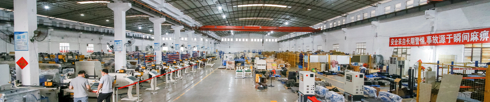
Complex tube components are central to many automotive and aerospace designs because they can carry load, transport air or fluid, and fit through constrained spaces at the same time. Traditional fabrication often joins several bent tubes, machined pieces, and stamped sections. That approach remains useful, but it can introduce welds, weight, dimensional stack-up, and inspection effort. Internal high-pressure forming, commonly called IHPF or hydroforming, offers another route: a tubular blank is placed in a die and formed from the inside with controlled fluid pressure, sometimes together with axial feeding or local end movement.
The process can create expanded sections, branches, offsets, and integrated contours that are difficult to make with bending alone. For automotive and aerospace applications, the appeal is not simply a more unusual shape. The process can enable a component with fewer joints, a more continuous load path, and a better relationship between material distribution and structural demand. Engineers must still confirm material behavior, fatigue performance, corrosion requirements, sealing strategy, and inspection access before selecting IHPF.
How internal high-pressure forming works
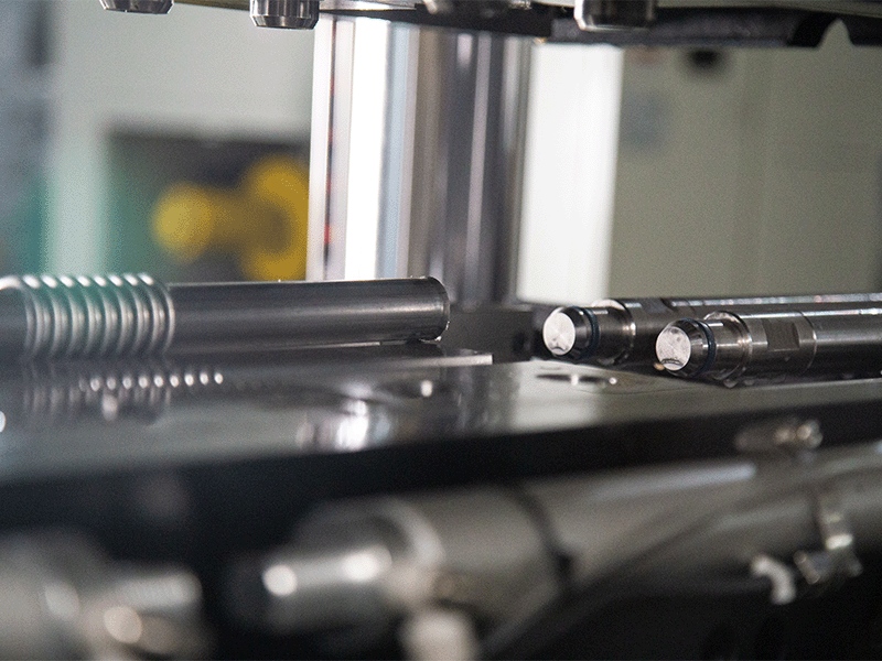
GSIE Single Bellow Hydro-Forming Machine
GSIE's current IHPF category includes a Single Bellow Hydro-Forming Machine. Its page describes high-pressure water expansion followed by servo-driven screw movement to close the molds and form corrugated pipe, so the process should be matched to the target geometry rather than treated as a generic pressure operation.
An IHPF cycle begins with a tube blank prepared to a defined length and condition. The blank is positioned in a matched die, and the ends are sealed by axial cylinders or end units. The forming medium is introduced and pressure rises according to a controlled recipe. As the tube expands against the die, axial feeding can supply material to regions that would otherwise become too thin. The pressure and feed path must be coordinated with the material's forming limit, the target geometry, and the friction conditions in the die.
After forming, pressure is released in a controlled manner, the part is removed, and critical features are inspected. The exact sequence varies by material and design. Some components may require pre-bending, local end forming, trimming, piercing, or calibration before or after the high-pressure step. The process plan should therefore cover the complete component route rather than treating the pressure cell as a standalone press.
Why IHPF can outperform assembled fabrication
The first advantage is geometric integration. A single formed part may replace several pieces that would otherwise need cutting, fixtures, welding, and finishing. Fewer joints can reduce leak paths and simplify the inspection plan. In a structural application, a continuous profile may also distribute loads more smoothly than an assembly with multiple welded transitions. In a fluid application, eliminating unnecessary joints can support reliability when the design and process controls are appropriate. This is especially relevant when the design target is lightweight, high-strength parts with fewer interfaces.
The second advantage is weight management. Internal pressure can place material where the design needs a larger section while allowing other regions to remain relatively light. This is useful for vehicle structures, suspension-related components, cross members, and selected aerospace tube assemblies. The resulting component may achieve the required stiffness or strength with less mass, but the claim must be demonstrated through engineering analysis and physical testing. IHPF is a design-enabling process, not a guarantee of weight reduction in every part.
The third advantage is dimensional repeatability when the die and process are well controlled. The die defines the external contour, and pressure, axial feed, and material preparation determine how the blank reaches it. Sensors can record pressure, position, force, and cycle status. With a validated recipe, the manufacturing team can detect drift earlier than it might with a largely manual multi-operation route. The quality system should connect those process values to the finished part and its material lot.
The role of bending and end preparation
IHPF usually works best when the upstream tube condition is controlled. A CNC mandrel bender may be used to create a pre-bent blank that fits into a complex die or to establish the orientation of a branch area. The bend must preserve enough material formability for the subsequent pressure operation. A CNC tube bending machine can provide the position and rotation repeatability needed for this preparation. Excessive flattening, wall thinning, or residual stress can reduce the available process window.
End preparation is equally important. An end forming machine can create the diameter, bead, flare, or locating profile needed for sealing and axial clamping. Accurate end geometry helps the pressure cell seal reliably and makes loading repeatable. A pipe forming machine may be used for related reductions or expansions, but the tool should be selected around the actual material and connection requirement. It is better to validate a short, controlled preparation sequence than to add operations that do not improve the final component.
The upstream and downstream route may also include dedicated tube bending equipment for other variants in the same product family. Keeping these interfaces standardized makes it easier to compare IHPF with conventional fabrication and to reuse validated handling and inspection methods.
Materials and process window
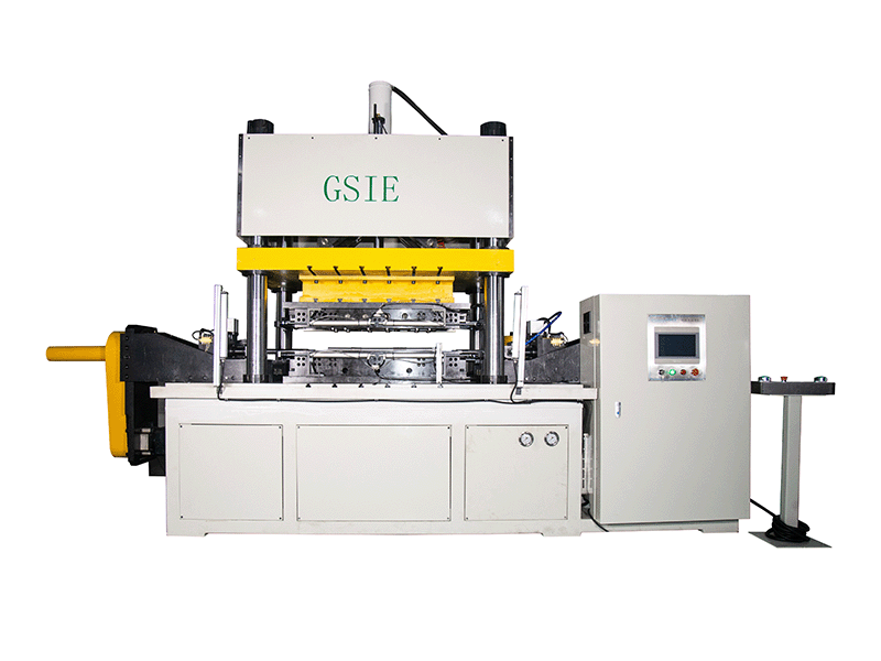
GSIE BM30-600 servo bellows water expansion machine
Validated material behavior, tooling, pressure control, and inspection should determine whether IHPF is the right route for a complex tube component.
Conclusion
Internal high-pressure forming is most effective when the part design, material behavior, tooling, pressure control, and inspection plan are considered together. It can reduce joints and create complex tube geometry, but the process window must be proven on the actual component.
GSIE, supports this process with Internal High-Pressure Forming solutions and related Single Bellow Hydro-Forming Machine equipment. Upstream preparation can be coordinated with GSIE's CNC Tube & Pipe Bending Machine and Tube End Forming Machine solutions, giving manufacturers a practical route from tube preparation to controlled forming.